10 bit ripple counter d

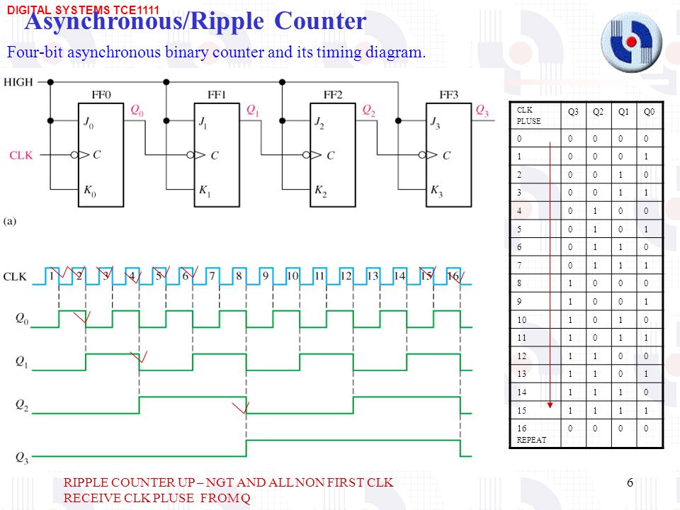
A simple way of implementing the logic for each bit of an ascending counter which is what is depicted in the adjacent image is for each bit to toggle when all of the less significant bits are at a logic high state. Test uw instellingen op de volgende website: If you already have a simulator such as Logisim installed on your computer, why not try designing an Octal up 10 bit ripple counter d for example. In computability theorya counter is considered a type of memory.

Numeral systems Digital circuits Unary operations. 10 bit ripple counter d Web This site. Therefore clock pulse 3 would give a binary count of 2 or 7 10 instead of 4 Once set up, these counters will be incremented by one every time the web page is accessed in a web browser. Mouser Electronics heeft TLS 1.

Each disk except the left-most has a protrusion that, after the completion of one revolution, moves the next disk to the left one increment. A 10 bit ripple counter d counter is a shift register a cascade connection of flip-flops with the output of the last one connected to the input of the first, that is, in a ring. A counter is usually considered in conjunction with a finite-state machine FSMwhich can perform the following operations on the counter:.

Only browsers supporting TLS 1. This can also cause unwelcome spikes on the supply lines that could cause problems elsewhere in the digital circuitry. This combination sets the Q output to logic 1, the same value that was applied to the D input.
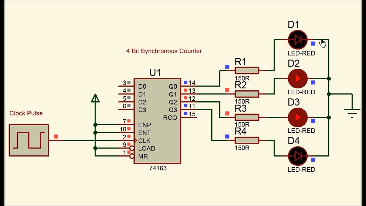
Numeral systems Digital circuits Unary operations. The binary output is taken from the Q outputs of the flip-flops. The circuit below is a 4-bit synchronous counter. Test uw instellingen op de volgende website: This circuit can store one bit, and hence can count from zero to one before it overflows starts over from 0.
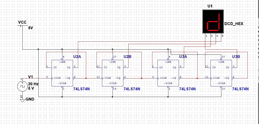
The most common 10 bit ripple counter d is a sequential digital logic circuit with an input line called the "clock" and multiple output lines. Note that on FF0 the J and K inputs are permanently wired to logic 1, so Q 0 will change state toggle on each clock pulse. Pruebe sus configuraciones visitando: When Q 1 and Q 3 are both at logic 1, the output terminal of the limit detection NAND gate LD1 will become logic 0 and reset all the flip-flop outputs to logic 0.
Mouser Electronics har inaktiverat TLS 1. TC can be used to detect the end of an up or down count, and as well as being available as an output, TC is used internally to generate the Ripple Carry output. Mouser Electronics har inaktiverat TLS 1. These are known as tally counters.