Verilog code for 3 bit ripple carry adder example
A multiple bit adder which adds two numbers having multiple bits. Instantiate Full Adder modules. To make n-bit ripple carry adder, we use generate block to implement a Full Adder module n timeswhere n is an integer. Every digital circuit has delay in operation time. Each Full Adder has a specific range of delay. Output depends on the number of bits or Full Adders in the circuit. With an increase in number of bits, the delay increases too.
Therefore with increase in combinational delay leads to verilog code for 3 bit ripple carry adder example in operating frequency. One of them is Kogge Stone Adderone of the fastest adders available.
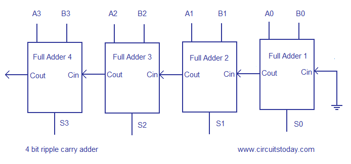
You are commenting using your WordPress. You are commenting using your Twitter account. You are commenting using your Facebook account. Notify me of new comments via email. Below is the schematic diagram of 4 bit Ripple Carry Adder. Disadvantage of Ripple Carry Adder: Many more adder architectures are developed by researchers. Leave a Reply Cancel reply Enter your comment here Fill in your details below or click an icon to log in: Email required Address never made public. Amrita School of Engineering, Bengaluru.
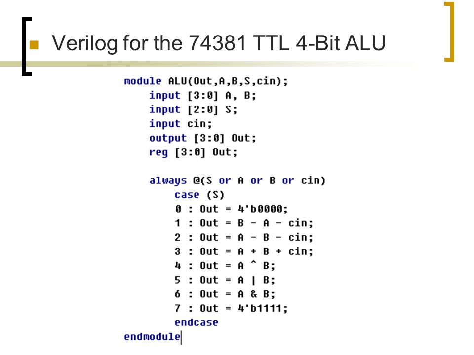
This lab should be done after the introduction lab on Verilog. It shows how to use two modules, one for the basic 3-bit full-adder adding a to b with carry-inand one that uses 4 of them to create a 4-bit adder with an output carry. A full adder is a combinational logic that takes 3 bits, aband carry-inand outputs their sum, in the form of two bits, carry-outand sum.
We now have several options to define verilog code for 3 bit ripple carry adder example adder. One is functionalas illustrated in the next subsection. Next is a logical description, where we express the outputs in terms of their logical equation. The final is a gate level description. Pick the one that seem most interesting to you. They should all yield the same result in the next section, where we test them. The timing diagram is fine, but a bit hard to read. A simpler test would be to have the simulation print out the value of the signals.
Rerun the simulation and observe the output in the console of the ISim application: We will now create a new Verilog module called MultiStages. The idea is simple. We want to add a 4-bit word to another 4-bit word and get a 4-bit sum, and a carry out. All we need to do is write Verilog code that will replicate the full-adder encapsulated in SingleStage 4 times, and let the carry ripple from one stage to the next. You should be able to recognize the main features of the test module by now.
The one that might be surprising is the for loop. Retrieved from " http: Navigation menu Personal tools Log in. Views Read View source View history. This page was last edited on 6 Aprilat Privacy policy About dftwiki Verilog code for 3 bit ripple carry adder example.

The market was inflated by people fleeing the vennizualian currency due to its massive devaluation.refuse withdrawals Every trader has the right to express his, her view about a broker, a robot. Bitcoin (add owner) CS: GO Skins (add owner) They Came from Moon Head Shot Why so Evil 1 Why so Evil 2 3x 16bit Trader 1x Dead Bits 4x Endorlight What are Crypto Robots.