2 bit ripple counter counting sequence
This counter will increment once for every clock cycle and takes two clock cycles to overflow, so every cycle it will alternate between a transition from 0 to 1 and a transition from 1 to 0. If this output is then used as the clock signal for a similarly arranged D flip-flop remembering to invert the output to the input , one will get another 1 bit counter that counts half as fast.
Putting them together yields a two-bit counter:. You can continue to add additional flip-flops, always inverting the output to its own input, and using the output from the previous flip-flop as the clock signal. The result is called a ripple counter, which can count to 2 n - 1 where n is the number of bits flip-flop stages in the counter. Ripple counters suffer from unstable outputs as the overflows "ripple" from stage to stage, but they do find frequent application as dividers for clock signals, where the instantaneous count is unimportant, but the division ratio overall is to clarify this, a 1-bit counter is exactly equivalent to a divide by two circuit; the output frequency is exactly half that of the input when fed with a regular train of clock pulses.
The use of flip-flop outputs as clocks leads to timing skew between the count data bits, making this ripple technique incompatible with normal synchronous circuit design styles. In synchronous counters, the clock inputs of all the flip-flops are connected together and are triggered by the input pulses. Thus, all the flip-flops change state simultaneously in parallel. The circuit below is a 4-bit synchronous counter.
A simple way of implementing the logic for each bit of an ascending counter which is what is depicted in the adjacent image is for each bit to toggle when all of the less significant bits are at a logic high state. For example, bit 1 toggles when bit 0 is logic high; bit 2 toggles when both bit 1 and bit 0 are logic high; bit 3 toggles when bit 2, bit 1 and bit 0 are all high; and so on. Synchronous counters can also be implemented with hardware finite-state machines , which are more complex but allow for smoother, more stable transitions.
A decade counter is one that counts in decimal digits, rather than binary. A decade counter may have each that is, it may count in binary-coded decimal , as the integrated circuit did or other binary encodings. An ordinary four-stage counter can be easily modified to a decade counter by adding a NAND gate as in the schematic to the right. It counts from 0 to 9 and then resets to zero. The counter output can be set to zero by pulsing the reset line low. The count then increments on each clock pulse until it reaches decimal 9.
When it increments to decimal 10 both inputs of the NAND gate go high. The result is that the NAND output goes low, and resets the counter to zero. A ring counter is a circular shift register which is initiated such that only one of its flip-flops is the state one while others are in their zero states. A ring counter is a shift register a cascade connection of flip-flops with the output of the last one connected to the input of the first, that is, in a ring.
Typically, a pattern consisting of a single bit is circulated so the state repeats every n clock cycles if n flip-flops are used. These counters find specialist applications, including those similar to the decade counter, digital-to-analog conversion, etc.
They can be implemented easily using D- or JK-type flip-flops. In computability theory , a counter is considered a type of memory. A counter stores a single natural number initially zero and can be arbitrarily long. A counter is usually considered in conjunction with a finite-state machine FSM , which can perform the following operations on the counter:.
The following machines are listed in order of power, with each one being strictly more powerful than the one below it:. For the first and last, it doesn't matter whether the FSM is a deterministic finite automaton or a nondeterministic finite automaton. They have the same power. The first two and the last one are levels of the Chomsky hierarchy.
The first machine, an FSM plus two counters, is equivalent in power to a Turing machine. See the article on counter machines for a proof. A web counter or hit counter is a computer software program that indicates the number of visitors, or hits, a particular webpage has received. Such control enable can be realized by setting, for example, the J and K inputs of a J-K flip-flop. Because of this control, the addition of a common clock will synchronize data transfer and all flip-flops will change state simultaneously.
The important feature of a synchronous counter is that the transitions of the individual flip-flops are synchronized to a master clock signal.
J-K flip-flops are normally used in the synchronous counters due to the enabling controlling feature of the J and K inputs. There are two basic schemes for generating the J and K inputs.
One of them is illustrated in the four-bit binary counter shown in Fig. Notice that the information to the J-K inputs is formed in a parallel fashion. The counter is accordingly termed as synchronous parallel counter.
In the parallel scheme the number of inputs to each AND gate increases linearly with the number of stages. For this added expense one gets the fastest possible synchronous counting circuit.
If the J-K input information is formed from the output of the AND gate in the previous stage, one has a synchronous serial counter. Although the serial scheme is slower than the parallel scheme, the number of inputs to the AND gate per stage is constant in the serial case two inputs per stage.
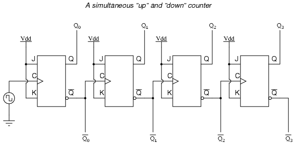
Connect the count-up ripple counter shown in Fig. Set data switch SW1 from logic 0 to logic 1 clear all flip-flops. Now connect CLK to a pulse generator in your pencil box J-K flip-flops in 74LS76 are negative edge triggered and start counting by pushing the pulser button. Continue the process and record the output of each transition in a truth table.
Does it count correctly? We can convert the count-up ripple counter to a count-down ripple counter by connecting the clock of the flip-flops to Q instead of Q the LEDs are still connected to Q. Make the modification and try out the circuit. Connect the 4-bit synchronous parallel counter as shown in Fig.