Pumps in series increase pressure of liquid

Centrifugal pumps are a sub-class of dynamic axisymmetric work-absorbing turbomachinery. The rotational energy typically comes from an engine or electric motor. The fluid enters the pump impeller along or near to the rotating axis and is accelerated by the impeller, flowing radially outward into a diffuser or volute chamber casingfrom where it exits. The reverse function of the centrifugal pump is a water turbine converting potential energy of water pressure into mechanical rotational energy.
According to Reti, the first machine that could be characterized as a pumps in series increase pressure of liquid pump was a mud lifting machine which appeared as early as in a treatise by the Italian Renaissance engineer Francesco di Giorgio Martini. The curved vane was introduced by British inventor John Appold in Like most pumps, a centrifugal pump converts rotational energy, often from a motor, to energy in a moving fluid.
A portion of the energy goes into kinetic energy of the fluid. Fluid enters axially through eye of the casing, is caught up in the impeller blades, and is whirled tangentially and radially outward until it leaves through all circumferential parts of the impeller into the diffuser part of the casing. The fluid gains both velocity and pressure while passing through the impeller.
The doughnut-shaped diffuser, or scroll, section of the casing decelerates the flow and further increases the pressure. It is important to note that the water is not pushed radially outward by centrifugal force non-existent forcebut rather by Inertiathe natural tendency of an object to continue in a straight line tangent to the radius when traveling around circle.
Pumps in series increase pressure of liquid can be compared to the way a spin-cycle works in a washing machine. Accordingly, the change of the angular momentum is equal to the sum of the external moments.
Since no pressure forces are created on cylindrical surfaces in the circumferential direction, it is possible to write Eq. The color triangle formed by velocity vector u,c,w called "velocity triangle".
This rule was helpful to detail Eq. It illustrates rather clearly energy added to the flow shown in vector c inversely change upon flow rate Q shown in vector c m. Vertical centrifugal pumps are also referred to as cantilever pumps. They utilize a unique shaft and bearing support configuration that allows the volute to hang in the sump while the bearings are outside the sump.
This style of pump uses no stuffing box to seal the shaft but instead utilizes a "throttle bushing". A common application for this style of pump is in a parts washer. In the mineral industry, or in the extraction of oilsand, froth is generated to separate the rich minerals or bitumen from the sand and clays.
Froth contains air that tends to block conventional pumps and cause loss of prime. Over history, industry has developed different ways to deal with this problem.
In the pulp and paper industry holes are drilled in the impeller. Air escapes to the back of the impeller and a special expeller discharges the air back to the suction tank. The impeller may also feature special small vanes between the primary vanes called split vanes or secondary vanes. Some pumps may feature a pumps in series increase pressure of liquid eye, an inducer or recirculation of pressurized froth from the pump discharge back to the suction to break the bubbles.
A centrifugal pump containing two or more impellers is called a multistage centrifugal pump. The impellers may be mounted on the same shaft or on different shafts. At each stage, the fluid is directed to the center before making its way to the discharge on the outer diameter. For higher pressures at the outlet, impellers can be connected in series. For higher flow output, impellers can be connected in parallel. A common application of the multistage centrifugal pump is the boiler feedwater pump.
For example, a MW unit would require two feedpumps in parallel. All energy transferred to the fluid is derived from the mechanical energy driving the impeller.
This can be measured at isentropic compression, resulting in a slight temperature increase in addition to the pressure increase. The energy usage in a pumping installation is determined by the flow required, the height lifted and the length and friction characteristics of the pipeline.
The energy usage pumps in series increase pressure of liquid determined by multiplying the power requirement by the length of time the pump is operating. These are some difficulties faced in centrifugal pumps: An oilfield solids control system needs many centrifugal pumps to sit on or in mud tanks. The types of centrifugal pumps used are sand pumps, submersible slurry pumps, shear pumps, and charging pumps.
They are defined for their different functions, but their working principle is the same. Magnetically coupled pumps, or magnetic drive pumps, vary from the traditional pumping style, as the pumps in series increase pressure of liquid is coupled to the pump by magnetic means rather than by a direct mechanical shaft. The pump works via a drive magnet, 'driving' the pump rotor, which is magnetically coupled to the primary shaft driven by the motor.
They have no direct connection between the motor shaft and the impeller, so no gland is needed. There is no risk of leakage, unless the casing is broken. Since the pump shaft is not supported by bearings outside the pump's housingsupport inside the pump is provided by bushings. The pump size of a magnetic drive pumps can go from few Watts power to a giant 1MW. Most centrifugal pumps are not self-priming.
In other words, the pump casing must be filled with liquid before the pump is started, or the pump will not be able to function. If the pump casing becomes filled with vapors or gases, the pump impeller becomes gas-bound and incapable of pumping.
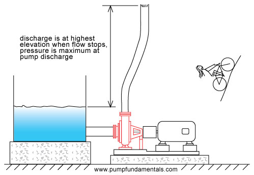
To ensure that a centrifugal pump remains primed and does not become gas-bound, most centrifugal pumps are located below the level of the source from which the pump is to take its suction.
The same effect can be gained by supplying liquid to the pump suction under pressure supplied by another pump placed in the pumps in series increase pressure of liquid line.
In normal conditions, common centrifugal pumps are unable to evacuate the air from an inlet line leading to a fluid level whose geodetic altitude is below that of the pump. Self-priming pumps have to be capable of evacuating air see Venting from the pump suction line without any external auxiliary pumps in series increase pressure of liquid. Centrifugal pumps with an internal suction stage such as water jet pumps or side channel pumps are also classified as self-priming pumps.
Centrifugal pumps which are not designed with an internal or external self-priming stage can only start to pump the fluid after the pump has initially been primed with the fluid.
Sturdier but slower, their impellers are designed to move water which is far denser than air, leaving them pumps in series increase pressure of liquid to operate when air is present. In self-priming centrifugal pumps with a separation chamber the fluid pumped and the entrained air bubbles are pumped into the separation chamber by the impeller action.
The air escapes through the pump discharge nozzle whilst the fluid drops back down and is once more entrained by the impeller. The suction line is thus continuously evacuated. The design required for such a self-priming feature has an adverse effect on pump efficiency. Also, the dimensions of the separating chamber are relatively large.
For these reasons this solution is only adopted for small pumps, e. More frequently used types of self-priming pumps are side channel and water ring pumps. Another type of self-priming pump is a centrifugal pump with two casing chambers and an open impeller. This pump type operates without a foot valve and without an evacuation device on the suction side. The pump has to be primed with the fluid to be handled prior to commissioning.
Two-phase mixture is pumped until the suction line has been evacuated and the fluid level has been pushed into the front suction intake chamber by atmospheric pressure. During normal pumping operation this pump works like an ordinary centrifugal pump. From Wikipedia, the free encyclopedia.
This article needs additional citations for verification. Please help improve this article by adding citations to reliable sources. Unsourced material may be challenged and removed. March Learn how and when to remove this template message. Centrifugal Pumps 2nd ed. Practical centrifugal pumps design, operation and maintenance 1. Retrieved 3 April Know and understand centrifugal pumps. Pump Sales Direct Blog. Retrieved from " https: Pumps Gas compressors Turbines Hydraulic engineering Power engineering.
Articles needing additional references from March All articles needing additional references Articles containing video clips. Views Read Edit View history. In other projects Wikimedia Commons. This page pumps in series increase pressure of liquid last edited on 3 Julyat By using this site, you agree to pumps in series increase pressure of liquid Terms of Use and Privacy Policy.
Look up Centrifugal pump in Wiktionary, the free dictionary. Wikimedia Commons has media related to Centrifugal pumps.
Most aspects of a pump's performance can be associated with the flow of fluid through the pump. Understanding pump performance involves a basic knowledge of pump specifications and pump performance curves. Pump operation and performance can best be described by a few fundamental parameters; flow rate, pressure, head, power, and efficiency. Volume flow rate Qalso referred to as capacity, is the volume of liquid that travels through the pump in a given time measured pumps in series increase pressure of liquid gallons per minute or gpm.
It defines the rate at which a pump can push fluid through the system. When selecting pumps, the flow rate or rated capacity of the pump must be matched to the flow rate required by the application or system. Pressure is a measure of resistance: The pressure rating of a pump defines how much resistance it can handle or overcome. It is usually given in bar or psi pounds per square inch.
Pressure, in conjunction with flow rate and power, is used to describe pump performance. Centrifugal pumps, however, typically use head described below instead of pressure to define the energy or resistance pumps in series increase pressure of liquid the pump, since pressure in a centrifugal pump varies with the pumped fluid's specific gravity.
When selecting pumps in series increase pressure of liquid, the rated operating or discharge pressure of the pump must be equal to or more than the required pressure for the system at the desired flow rate. Pump head H can be converted to pressure P using the specific gravity SG of the fluid by the equation:.
When selecting centrifugal pumps, the rated pump head must be equal to or greater than the total head of the system total dynamic head or TDH at the desired flow rate. Pump head in a centrifugal pump will be the same for all liquids if the shaft is spinning at the same speed. The only difference between fluids pumps in series increase pressure of liquid the amount of power needed to get the shaft to the proper speed rpm.
The higher the fluid's specific gravity SGthe more power is required. Another specification to consider is net positive suction head NPSH - the difference between the pump's inlet stagnation pressure head and the vapor pressure head.
The required NPSH is an important parameter in preventing cavitation in a pump. Cavitation happens inside a pump when the local pressure falls below the vapor pressure of the liquid being pumped, causing the liquid to boil. The pressure inside the pump should be above the NPSH to avoid cavitation, which can result in noise, vibration, reduced efficiency, and damage to impeller blades. Net head is proportional to the power actually delivered to the fluid, called output power P out or the water horsepower measured in horsepower or hp.
This is the horsepower rating which describes the useful work the pump will do to the fluid. It can be calculated by the equation:.
In all pumps there are losses due to friction, internal leakage, flow separation, etc. Because pumps in series increase pressure of liquid these losses, the external power supplied to the pump, called the input power Pin or brake horsepower, is always larger than the water horsepower. This specification is typically provided by the pump manufacturer as a rating or in the pump's performance curve and is used to select the proper motor or power source for the pump.
When determining the required power from a typical pump performance curve discussed belowit is best to use the values at the end of the curve to ensure adequate supply at most operating conditions.
For operations with little system variation e. It is the ratio between the water horsepower and brake horsepower useful power vs. Keep in mind that any efficiency rating of the pump given by the manufacturer assumes certain system conditions such as the type of fluid transported: The efficiency pumps in series increase pressure of liquid not be accurate if these assumptions differ from the consumer's intended application.
A more efficient pump is not always the best choice when considering energy costs. All pumps have a characteristic or performance curve that describes the flow rate produced at net or total head. Pump specifications relating head and flow rate correlate to those found on pumps in series increase pressure of liquid characteristic curve.
A simplified curve for a centrifugal pump will look something like this:. The pump curve illustrates the available total head at a given flow rate of the pump. Generally, more head is available in the pump as flow rate decreases. Manufacturers usually designate an optimum or best efficiency point BEP of the curve, which is indicated in this graph by the dotted line. Thus, this pump runs best when supplying a net head of ft, which will provide a flow pumps in series increase pressure of liquid of 23 gpm.
When selecting a pump for incorporation into a system, users should map the system curve alongside the pump curve. A simplified incorporation of this curve may look something like this:. The system curve illustrates the required head for different flow rates in the system. It is constructed using a form of Bernoulli's equation for fluid mechanics, which is beyond the scope of this guide. Generally, more head is required as flow rate increases due to frictional forces and other losses in the system.
The operating point of the pump in a system should be where the pump curve and system curve intersect. Since every system is unique and has specific head requirements, the ideal choice mentioned above is not always commercially available. Positive displacement pumps do not utilize fluid momentum, meaning that flow rate is relatively independent of pump head.
Thus, unlike dynamic pumps positive displacement pumps have a definite capacity across a wide range of head pressures as shown in the characteristic curve below. Slippage is the result of high discharge pressures causing some liquid to leak back to the pump suction, reducing capacity. Information About Pump Flow. Pump Flow Most aspects of a pump's performance can be associated with the flow of fluid through the pump.
Pump Parameters Pump operation and performance can best be described by a few fundamental parameters; flow rate, pressure, head, power, and efficiency. In the confines of a pump during operation, cavitation to an impeller can be much more devastating.
Top Categories Terms of Use.