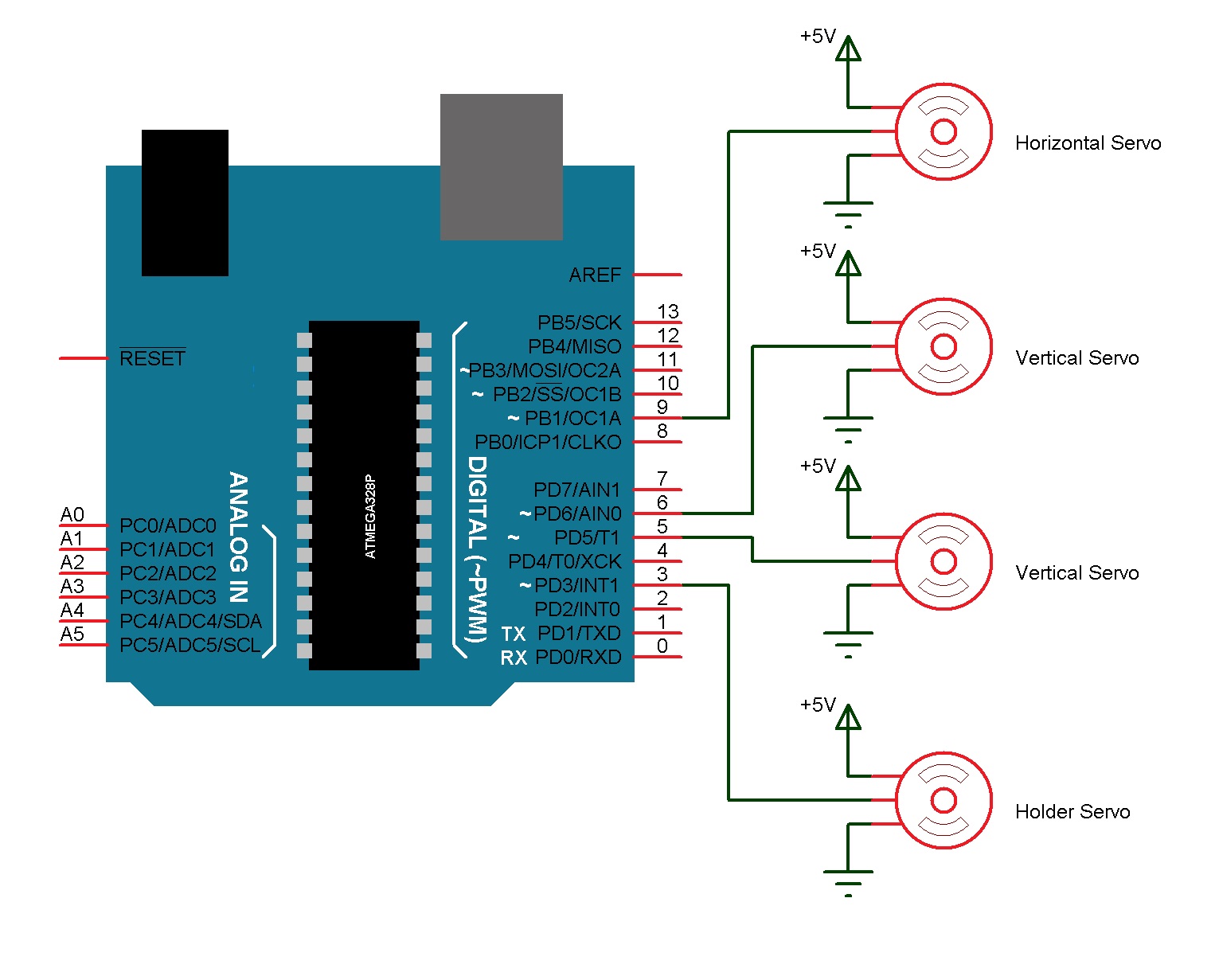
Robot arduino nano board layout

When this line is asserted taken low , the reset line drops long enough to reset the chip. The DFRduino software uses this capability to allow you to upload code by simply pressing the upload button in the DFRduino environment. This means that the bootloader can have a shorter timeout, as the lowering of DTR can be well-coordinated with the start of the upload. This setup has other implications.
For the following half-second or so, the bootloader is running on the Nano. While it is programmed to ignore malformed data i. If a sketch running on the board receives one-time configuration or other data when it first starts, make sure that the. Discussion View source History.
Arduino Nano SKU: Retrieved from " https: This page was last modified on 19 March , at The Nano automatically senses and switches to the higher power supply, so there is no need for a power select jumper. The power source is automatically selected to the highest voltage source.
As a result, when running on external non-USB power, the 3. Each of the 14 digital pins on the Nano can be used as an input or output, using pinMode , digitalWrite , and digitalRead functions. They operate at 5 volts. Each pin can provide or receive a maximum of 40 mA and has an internal pull-up resistor disconnected by default of kOhms. In addition, some pins have specialized functions:.
These pins can be configured to trigger an interrupt on a low value, a rising or falling edge, or a change in value. See the attachInterrupt function for details. Provide 8-bit PWM output with the analogWrite function. These pins support SPI communication, which, although provided by the underlying hardware, is not currently included in the DFRduino language.
Just solder some header pins on the board and wire them up. Oh no I was asking where to find that perfboard I didn't know what it was at the time. Our chat is a buzzing-with-life place where our community members join to discuss and foster great conversations. Whether it's about their latest robotics project, questions about electronics, debates about the industry, or just talking between friends. Arduino Nano on PCB. By lumi November 8, Why I did this? However, the reason ist not the important thing here, but how to do it.
First thing was cutting a matching piece of PCB, male and female header pins and some wire. Then solder the header pins on the PCB. This is pretty much all I've done. For the current project I do not need more.
Comment viewing options Flat list - collapsed Flat list - expanded Threaded list - collapsed Threaded list - expanded. Date - newest first Date - oldest first. Select your preferred way to display the comments and click "Save settings" to activate your changes. By Chris the Carpenter Wed, By lumi Wed, Hi brother ;- Yeah, the thing with this board is that it can be expanded