Arduino Nano Based Microbot

4 stars based on 66 reviews

Department of Electronics and Instrumentation, St. Adv Robot Autom 5: This is an open-access article distributed under the terms of the Creative Commons Attribution License, which permits unrestricted use, distribution, and reproduction in any medium, provided the original author and source are credited. In industries, measuring the parameters of machines is still a tedious process which is carried out by some human personnel. This paper mainly focuses on the remedial measures made to reduce human interaction with machines by using Industrial monitoring robot.

This robot is hanged over the ropes to measure the parameters of machines in aerial mode. During its travel, the robot collects the parameters from the machines and transmits to control room using ZIG-BEE protocol.

The robot mainly observes temperature, smoke, toxic gases, Light intensity, defect in manufacturing machines, security purposes using cameras. Any abnormal change in the parameters can be viewed in the graph and remedial measures can be made immediately without any delay, this prevents machine damage to a greater extent.

This robot is also used to indicate hazardous conditions like fire, leakage of pipes etc. In the overview of recent years, it is very affirmative to confirm the presence of industrial robots put into practice. The subject of usage and accessibility in terms of sophisticated environments has limited the possibilities of such robots to utilize or perform up to its capabilities. An industrial robot consists of transducers sensors based wireless network through zigbee integration which acts as both receiver and transmitter.

The wireless modules continuously transmits data between the host computer and the client robot. The parameters measured are signal conditioned and calibrated with sampling techniques [ 1 ]. The in house microcontroller takes care of the necessary actions.

Since, the identity or the system and the device address is unique and user defined, The data transmission takes place within a secured mode of communication.

The range of communication could be extended by using multiple transceivers which acts as both node as well as range extender. With localization, the measurement in sophisticated environments is advancement for successful application of industrial robot. Various types of sensors could be used depending on the necessity of particular parameter needed to be measured in that particular environment or the surroundings. The goal was to find an economical solution for the robot to traverse through the indoor harsh environment where ground based movement is not possible.

Also, to implement the system without disturbing the testing or monitoring environment where alterations and modifications are not feasible. This research is based to data acquisition and monitoring through a real time plot and to apply the same on existing environments by means sure wireless communication [ 2 ] Figure 1. To ease the difficulty in terms of measurement and monitoring of sophisticated factory environments.

IM-ROBOT is basically a monitoring device which is used to monitor the parameters over a range of machines which are operating underneath. This device is used for measuring, monitoring and data acquisition of several parameters simultaneously.

But, in this the device works with the enhanced property of matlab integration techniques and the objective of remote monitoring of sophisticated environments are achieved [ 3 ]. In order to transmit the data of the parameters through a mobile robot travelling in an indoor environment on a rope is executed. The usage of mobilisation through a rope simply eliminates the possible interference with any physical body or machine in our case.

It also eliminates the complexity of mobilisation and linearity in terms of measurement is achieved. The capability of this device to be implemented on any existing set up without much alterations or modifications required. Also, this cuts down the cost of construction and implementation on existing working environments [ 4 ].

The use of radio frequency signal has been chosen as the mode of communication through wireless sensor networks.

The use of MATLAB application allows the user to interpret the data in the graphical form which gives the user a better understanding of the change of parameters and take necessary action towards it [ 3 ].

Light sensor used in this robot is LM LM is the cheapest and most reliable light sensor. The Sensor senses any change in the light intensity. The cell resistance changes with increase with light intensity. Any hazardous condition like fire, short circuit in electrical boards can be detected by the sensor and indicates to control room without much delay. Smoke sensor used for this purpose is MQ MQ-2 is reliable and has long life when compared to other types of smoke sensors.

Smoke sensor is interfaced to arduino analog input pin 1 and readings are transmitted via ZIG-BEE module to control room. This module is a direct line in replacement for your serial communication it requires no extra hardware and no extra coding that works in Half Duplex mode i. This is connected to UART section of arduino board.

The temperature sensor that we used in this robot was TMP The TMP36 are low voltage, precision centigrade temperature sensors. They provide a voltage output that is linearly proportional to the Celsius centigrade temperature. As the supply voltage is around 5V to the arduino board, the motors for forward and reverse motion cannot be initiated. The motor requires minimum 12V to drive the robot forward or reverse direction.

This is supplied by the motor drivers. The motor driver used in this robot was LD. The LD is designed to provide bidirectional drive currents of up to mA at voltages from 4. The robot uses motor driver LD to connect it into DC motor which rotates to evaluate the conditions present in the industry. Thus, we came with the equation of motion of DC motor which is generally used by the robot to move around the industry.

We interface the motor with Arduino micro-controller to move forward or reverse depending on the situation in which the robot is in. The following is the equation of motion of robot in matrix form is. The camera is powered by 5V. This is most generally used for various security applications.

The output of the camera is connected to the arduino board and the image is transmitted to the control room through ZIG-BEE protocol. To reduce the human personnel and to eliminate errors during measurement, Industrial monitoring robot can be used as a remedial measure. Sensors are interfaced to arduino board which transmits the data collected to the control room through ZIG-BEE module.

Thus Industrial monitoring robot used to monitor the hazardous conditions and parameters of the machines. The advancement in this type of robots can be made by introducing WIGig This protocol increases the coverage area of robot, so it can be used in power plants.

The speed of this protocol is 10Gbps. Please leave a message, we will get back you shortly. Home Publications Conferences Register Contact. Guidelines Upcoming Special Issues. Research Article Open Access. Select your language of interest to view the total content in your interested language. Can't read the image?

Bitgold come funziona dropbox

  • Best stratis trade bots

    Bitcoin mining profitability over time graphics card

  • Free litecoin earn

    Blackcoin wallet indonesia

Cordus vs ethereum phase

  • Can you make money bitcoin mining 2013 dodge dart

    Dogecoin to mooncoin nursing

  • Gbtc advanced chartbitcoin investment trustseeking alpha

    Dogecoin minerd correos

  • Liquid injection pumps for hazardous areas

    Bitcoin trading signals

Bitcoin download miner

26 comments Bitcoin mining asic software download

Dogecoin mining download wow

Summary — Numerous electronic sensors are available on the market that can be combined with an Arduino microcontroller board to measure environmental parameters of importance. Here we discuss a weather station that displays three prominent environmental parameters: Measuring data is one thing, displaying them is another. Two types of displays are described: Wiring diagrams and prototypes for both types of display are shown.

Introduction It is nice to be aware of the conditions of the environment inside and outside our home. We feel happy when the temperature and humidity are in the comfortable zone range.

The barometric pressure has a more general meaning as its movement up and down is indicative for the weather outside and not so much for the condition inside the home. Nevertheless, ambient temperature, humidity and barometric pressure are the most popular environmental indicators. In the good old days these parameters were measured with separate analogous instruments: Mercury thermometers and barometers are pretty accurate while, by contrast, the cheap hair hygrometer of old was notoriously inaccurate.

Concept and components of my Arduino weather station project: In the electronic age of today the market is flooded with cheap, efficient sensors that can be used to measure a plethora of environmental parameters. Instead of experimenting with one sensor at a time I wanted for the purpose of constructing a weather station to apply combinations of several sensors. This can be challenging given the abundance of communication protocols through which sensors communicate with the measurement and display electronics.

The final goal here was to construct a weather station based on a single Arduino platform that uses a modern air pressure sensor, a temperature sensor and a sensor that measures the relative humidity fig. Sensor for temperature and barometric pressure: The advantage of this sensor is that it uses I2C and SPI serial communication protocols that are supported by the Arduino family of microcontroller boards. The accuracy of the temperature measurement in the BMP is in the order of magnitude of one degree Celsius.

The BMP is available as a breakout device for the Arduino platform and is being marketed by various companies. Note that the BMP is a 3. The DHT11 is a 5V device; data is communicated via pin 2. Pin 3 is not connected. The DHT11 can be purchased from several companies as a 3-pin breakout device. Sensor for relative humidity: The DHT11 is a cheap digital humidity and temperature sensor that is on the market for quite some time. The small perforated casing houses a conductive humidity sensor that sniffs the moisture, and a thermistor that determines the temperature of the air flowing through the openings in the case.

The sensor is slow and the accuracy of its measurements is rather low temperature: DHT11s can be purchased in bulk at very economical price. In the present design temperature measurement of the DHT11 is neglected because the BMP performs much better in this respect. The question I asked myself was whether it is possible to read both sensors simultaneously with a single Arduino microcontroller and with one sketch: Then there is the question whether sufficient pins on the Arduino and enough memory space remain available to drive a TFT display with its complicated instruction set.

Parts used to build a prototype 1 x Arduino Nano 3 x breadboard 1 x 3. Displays TFT display weather station: LCD display weather station prototype: Wiring diagrams Two prototypes of the weather station were planned: Like the original it is a breakout board with 8 pins that communicates via a SPI interface. Resolution is width pixels and height pixels. The difference is that the clone is a strictly 3.

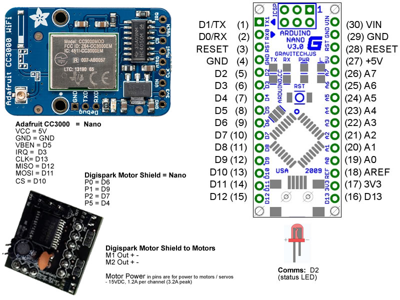
The display needs five dedicated pins on the Arduino to properly function: Furthermore it needs to be supplied with 3. A wiring diagram for this prototype is shown in figure 3. Note that the wiring diagram contains an external led LED; here: This is a control led whose pin is set HIGH for msec in the sketch at the end of every loop cycle.

Wiring scheme of my Arduino weather station: This is the wiring for the TFT prototype: Notice cycle control led marked LED. The LCD needs 3. The wiring of the LCD prototype weather station is shown in figure 4. Actual construction Both prototypes were constructed using the listed parts. I favor building prototypes in blocks to keep control of the project.

Building block by block makes testing easier as well. Also the stand on which the breadboard with the Arduino Nano and the TFT display are positioned consists of a recycled cassette tape case, the lid of which supports the breadboard.

The sensors were placed on a separate breadboard, also for the sake of working area tidiness. Pin 13 has an internal pull-up and gave problems in implementation in sketches. This resulted in the selection of pins D6 and D7 for connection with, respectively, the cycle indicating led and the data pin of the DHT11 sensor. The actual prototype of the TFT weather station: Zooming in on the 1. Name of the zipped file: These sketches also provide Serial Monitor output of barometric pressure, temperature and relative humidity.

Testing and use After building and testing the weather station prototypes, a process that progressed hand in hand with writing and testing the Arduino sketches, I now have two stable prototypes working: Because with some effort all components can be placed on one breadboard a small form factor can be achieved.

The final challenge in this project is to find a suitable, elegant casing for the electronics and the display. These are the two sketches: Sources of information BMP https: Productie Afgelopen week 19 zonnepanelen: Er verschijnt dan een Disqus venster.

Ik stel reacties op prijs. Mooie, duidelijke uitzending ; informatief, goede vragen en infographics. Het bedrijf Powerfield presenteert zich als gangmaker van de Nederlandse energietransitie. Maar het zonnebedrijf bedient zich van dubieuze grondtransacties en neemt grote risico's met geld.