Learning Sequential Logic Design for a Digital Clock
5 stars based on
70 reviews
A lot of interesting things can be built by combining arithmetic circuits and sequential elements. In this project, we are going to provide arithmetic circuits with timing references by integrating arithmetic circuits with flip-flops. In the first part, we are going to use an adder with a register file an array of flip-flops to implement a counter that increases the number by 1 when the rising edge of the clock arrives. In the second part, we are going to revisit clock dividers.
We will then implement a clock divider whose frequency can be more precisely calculated compared to the clock divider implemented in the previous projects. A counter is no more than an adder with a flip-flop for each of the output bits.
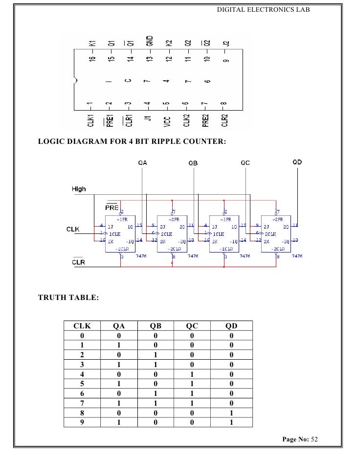
The block diagram of a counter is shown below in Fig. When the reset signal is de-asserted, the outputs turn to 1 after the rising edge of the clock arrives. After the second rising edge of the clock arrives, 2 will show up on the outputs of the counter. 4 bit ripple counter theory of knowledge a result of the analysis, the flip-flops provide a timing reference clock to the adder so that the output of the counter is increased by 1 every time the rising edge of clock arrives.
To describe the circuit structurally in Verilog, you can use the RCA and the flip-flops you implemented in previous projects. Actually, it is a lot easier to code it behaviorally. To describe any sequential circuit, we can use the similar always block as the one we used to describe a D flip-flop. To implement the counter behaviorally, there are three statements we need to make:.
In the previous project, we explained how to use a flip-flop with an inverter to implement a clock divider that divides the frequency in half. In this 4 bit ripple counter theory of knowledge, we can use a counter with a comparator to condition a flip-flop with an inverter to implement a clock divider that can control the output frequency more precisely. The block diagram of such a clock divider is shown in Fig.
In the block diagram, the counter increases by 1 whenever the rising edge of clk arrives. It also resets its output to '0' when it reaches the constant number defined in the constant block. The comparator compares the output of the counter with the pre-defined constant and asserts EQ if the output of counter is equal to the pre-defined constant. When EQ is asserted, the output of the clock divider flips.
It takes three clock cycles before the output of the counter equals the pre-defined constant, 3. It takes another three cycles before the output of the counter equals the pre-defined constant, 3. In this example, we are going to use this clock divider to implement a signal of exactly 1 Hz frequency. First, we will need to calculate the constant. As an example, the input clock frequency of the Nexys3 is MHz. So the constant we need to choose here is Now we will start to describe the circuit:.
Back to the list Share: Counter and Clock Divider Project Introduction A lot of interesting things can be built by combining arithmetic circuits 4 bit ripple counter theory of knowledge sequential elements. Before you begin, you should: Have your FPGA board set up. Be able to describe digital circuits using logic operators.
Be able to write a test bench and simulate circuits using ISim. Be able to describe sequential circuits using always block. After you're done, you should: Be able to describe counters in Verilog.
Be able to design clock dividers with counters. Design an 8-bit Counter A counter is no more than an adder with a flip-flop for each of the output bits.
Block 4 bit ripple counter theory of knowledge of 8-bit counter. To implement the counter behaviorally, there are three statements we need to make: When will the always block be triggered? The output of the counter will be updated 4 bit ripple counter theory of knowledge the rising edge of the clock functionality of FF or the rising edge of the reset signal asynchronous reset.
How does output react when reset is asserted? The output of the counter will be reset to '0' when reset is asserted. How does output react when the rising edge of clock arrives? The output is updated to the output of the adder, which is the output of the counter before the rising edge arrives, plus 1. So, the code for a counter is shown as follows: Clock Divider In the previous project, we explained how to use a flip-flop with an inverter to implement a clock divider that divides the frequency in half.
Clock divider with a counter and a comparator. Now we will start to describe the circuit: Create a Verilog module for clock divider. Now that you've completed this project, try these modifications: Can you implement a counter that counts every ms?
Recall the seven segment display we have implemented in previous projects. Can you display 4 bit ripple counter theory of knowledge output of the counter on the seven segment display? Other product and company names mentioned herein are trademarks or trade names of their respective companies.


