


Online poker using bitcoin exchanges
11 comments
How to make a asic bitcoin miner
Verilog Hardware description language. Hi, Design a two stage pipeline 16 bit s adder with verilog code, assume you can use the 8 bit adder macro module. The input and output signals are defined as: Take multiplication for example, I always invoke IPcore, except when come coefficients are constants then I'd use shift and add.
As to other operations such as cordic IPcore is my first choice Hi All I need to add a bit signal to a bit signal, and it won't generate carry bit. Since the clock is really fast, I'm trying to figure out how complex the adder logic might be, based on standard library from TSMC.
For example, will the critical path have more than 21 NAND-like level of combo cells? How can I code this multipler? Would I get some examples? Design a bit mutiplier. Hello all, I am trying to build a 4- bit full adder using 4 1- bit full adder s, with each full adder built from 2 1- bit half adder s may be it's not the most efficient way, but I'm trying this for educational purposes.
The code is as follows: Critical path and full adder scheme. Design Compiler DC Optimization commands to reduce negative slack? Hi, I tried to synthesize a bit adder. When I set the virtual clk to 1GHz. The timing report is clock vclk rise edge 1. I have no clue. Is this a jitter in output signals!? In transistor level, I simulated a 1- bit full adder cell and the transient response of output signals were ok, Until I tested it in a 16 cells successive full adder , a unstable state occured in outputs in specific transitions of inputs periodically picture attached.
This state has increased delay time. I dont know what is that, and The setup I am using and the Hobby Circuits and Small Projects Problems:: Full adder standard cell layout. Hello everyone , I would like to use a full adder standard cell in my project I am using Magic layout tool, I found one in the ssxlib library in vlsithechnology. Net has unmapped pin s. Hello, I'm trying to synthesize an adder. During synthesis, RTL compiler informed "Net has unmapped pin". However, synthesis still succeeded.
Then I checked the mapped netlist file. Surprisingly, there was no unmapped pins? Hello everyone, I am trying to design 32 bit binary signed digit adder but I am facing issue while writing code for signed number. The logic does not match a known FF or Latch template. I'm trying to implement only the functionality of the 8- bit adder using an always block. Ling adder and 4 bit redundant adder. Hi I am a bit confused when defining the i,j,k in the adder can any one help me to understand it regards uzmeed.
Please recompile with -mt off -v 1 swi. Altered Adder with binary output. Hello , I need your help here with something: I'm in quite a hurry so that's why I don't do it myself: I have to design a more intricate CLC and I did most part but at the very end I need a circuit that will add up to 11 1- bit signals to a 4- bit output that will give the number of 1s in binary.
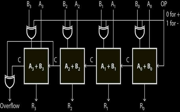
I request you to let me know if full subtractors are used in practice as opposed to implementing subtraction as two's complement addition. Need help with 8bits accumulator using 4bits adder. I need to construct an 8- bit accumulator. For this, I need an 8- bit adder. But my ASIC vendor? So I construct the accumulator.
When I synthesized the circuit, I found that there was a max-delay violation on the? Can anyone look into the code and suggest corrections? State Diagram for 4-bit Calculator. Hi, My assignment is to build a 4- bit calculator. Basically, the input is a keypad from 0 to F.
The components are the registers, full adder s and a BCD segment display. ALU that multiplies using asterix-Verilog. Due to my previous post got deleted somehow, this is my second post. Hello, First of all, I have a project that can do; It accomplishes all of this perfectly. However, now I need to edit my program in a way that it multiplies 2 numbers instead of add them I will take out add function and replace it w. Hi I make a tpr file that is for description of a one- bit full adder.
Also when I try to make a spice netlist, there is an other error about "n well wi. Parallel MAC unit design problems. The below diagram is the parallel MAC structure. In parallel MAC both partial product addition and accumulation take place at same time. For technical support on this issue, please open a WebCase with this project attached at.
I also got warning messages. To make long story short: To simplify let's assume that number of inputs is always a power of 2. My first idea is to build a binary tree of 2-input Hi everyone hope you are all fine.
I am new here please help me. How to deal with simulation with too many pins? Hi everyone, I have a question when I want to simulate a simple adder by cadence virtuoso.
I've designed a bit adder and would like to make a simulation. But it seems too boring when I do so because there are almost pins. I'm a bit curious about the current drawn from the supply of my full adder: How N-stage 4-bit Adder logic synthesis in Design Compiler. Now I need elaborate the design, don't know what type of adder is?
Can any tell me what type of adder come out from Synopsys Design Compiler. Can anyone to guide me for developing hspice code for 8- bit kogge-stone adder? Doubt regarding Parameters of the tree adders. What is the meaning of the 'k' in the equations for black cells used in adder s? Tried looking at many places Could someone explain with some example of a four bit adder? BCD Adder 4 Digit vhdl code. I made full adder. For further reduction in power consumption can i use 2: Plz can any one send me VHDL code for the following bit adder s: Does Google not work f.
It can be generalized as below. First of all, your picture is showing xA not 5. I think you may have your bit s backwards. B1 is your least-significant- bit. I wrote a code for the multiplication of two 8 bit numbers using shift operator and adder Problems with pill packaging project adder.
I presume, if you know how to implement a 4 bit adder , you basically know how to make a 8 or 16 bit adder , so it's not quite clear to me what you are exactly asking. I don't expect that you Modular 8 bit Ripple Carry Adder Help!