16 bit Ripple Carry Adder Verilog Code
4 stars based on
54 reviews
Enviado por Vanilson flag Denunciar. We will use this operator to write a multiplexer. Convince yourself that this description Example correctly models a multiplexer. The stimulus module will not change. The simulation results will be identical.
By encapsulating functionality inside a module, we can replace the gate-level module with a dataflow module without affecting the 4 bit ripple counter verilog modules in the simulation. This is a very powerful feature of Verilog. In this section, we write the dataflow description for the 4-bit adder.
Compare it with the gate-level description in Figure Then we built a 4-bit full ripple carry adder. We again illustrate two methods to describe a 4-bit full adder by means of dataflow statements. A Guide to Digital Design and Synthesis If we substitute the gate-level Cbit full adder with the dataflow Cbit full adder, 4 bit ripple counter verilog rest of the modules will not change. An n-bit ripple carry adder will have 2n gate levels.
The propagation time can be a limiting factor on the speed of the circuit. One of the most popular methods to reduce delay is to use a carry lookahead mechanism. Logic equations for implementing the carry lookahead mechanism can be found in any logic design book. The propagation delay is reduced to four gate levels, irrespective of the number of bits in the adder.
The Verilog description for a carry lookahead adder is shown in Example This module can be substituted in place of the full adder modules described before without changing any other component of the simulation. The simulation results will be unchanged. We design a 4-bit ripple counter by using negative edge- triggered flip-flops.
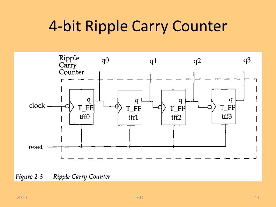
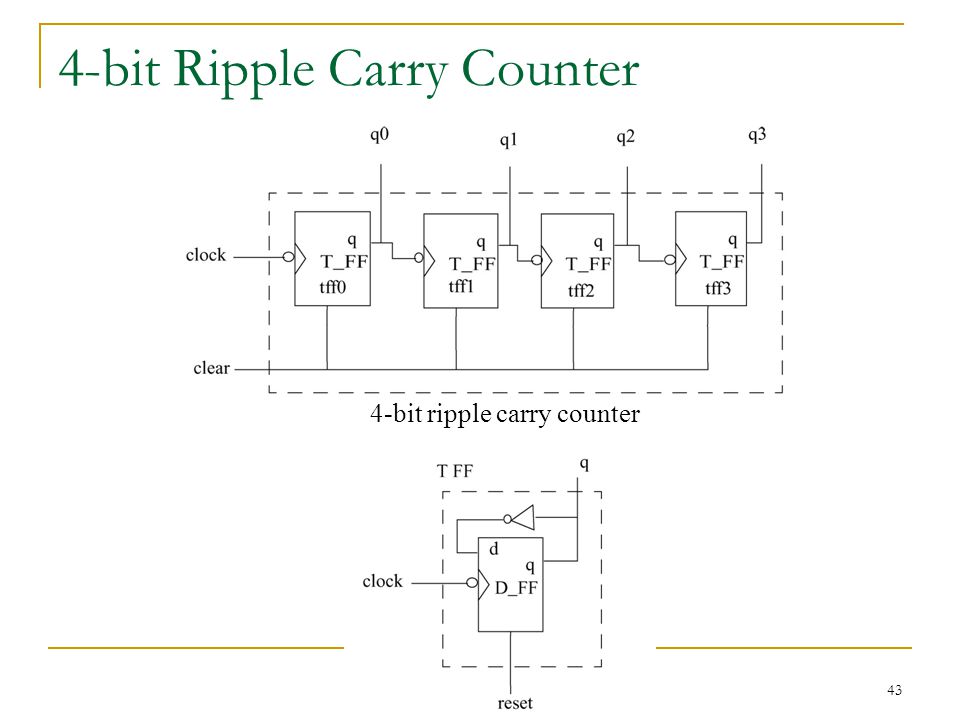
This example was discussed at a very abstract level in Chapter 2, Hierarchical Modeling Concepts. We design it using Verilog dataflow statements and test it with a stimulus module. The diagrams for the 4-bit ripple carry counter modules are shown below. Figure 4-bit Ripple Carry Counter Figure shows that the T-flipflop is built with one D-flipflop 4 bit ripple counter verilog an inverter gate.
First we design the module counter. The code is 4 bit ripple counter verilog in Figure The code contains instantiation of four T-FF modules. Notice that instead of the not gate, a dataflow operator - negates the signal q, which is fed back.
The dataflow statements correspond to the logic diagram shown in Figure The nets in the logic diagram correspond exactly to the 4 bit ripple counter verilog nets. Now we must instantiate.