Adiabatic Fluid Coolers
4 stars based on
78 reviews
This invention relates to improvements in the design of an adiabatic condenser or fluid cooler. More specifically this details two new control modes; energy savings mode and water savings mode; which are designed to optimize the use of these resources based on cost and availability.
This invention may be applied to units employing adiabatic saturation pads and also applied to units that employ any means to evaporate water such as spray nozzles before an indirect coil to reduce and cool the entering air temperature to the indirect coil. Prior ait adiabatic control systems use a combination of water and electrical energy to provide the necessary cooling required.
Electrical energy is used to drive the fans, which moves air through the coil s. Water is used to wet the adiabatic material and lower the temperature of the air passing through the coil. This prior art system saves energy over an air cooled system and saves water over an evaporative system by using the combination of resources.
Typical prior art condensers or fluid coolers can switch from dry to wet operation at a certain preset outdoor temperature or preset temperature or pressure condition; however, the prior art systems do not allow the savings of either water or energy resource to be optimized.
This invention allows the system to reduce the usage of the customer chosen resource either water or energy to the minimum level possible while still meeting the cooling demand. The system will favor the resource, either energy or water, that is less costly or less scarce at a given time. For example, if energy is determined to be scarcer or more costly, the system will use water whenever possible to minimize energy use.
If water is the scarcer or more costly resource, then the system will use water only when necessar to meet the heat rejection target. This invention also includes multiple methods for switching between the modes of operation. Mode selection can occur manually by changing a setting in the controls or can also be automated to provide the lowest utility usage cost for the user. Utility rates for electricity and water can be provided either manually or automatically via communications.
Another method for switching between modes is to accept a peak demand signal from a utility provider. This signal may be manually input or automatically sent by the utility.
When this signal is triggered, it would cause the unit to favor the resource that is not currently in peak demand typically electrical energy. This method of control would help to conserve scarce regional resources as well as reducing peak demand charges for the user.
For units employing adiabatic saturation cooler pads, this invention also includes the ability to increase the airflow through the coil when operating "dry". When running in the dry mode, the prior art product has a penalty of pressure drop through the adiabatic pads and consequently having reduced airflow through the unit. By bypassing air flow around the pads during dry operation, more airflow may be achieved thereby reducing fan motor energy usage and allows more conserving of water for longer periods of time.
Another feature of this invention is a coil cleaning program. This feature runs the fans backwards to force air through the coil in the opposite direction to force dirt and other debris out of the coil fins to improve the efficiency of the coil. This coil cleaning feature can be combined with a spray system on the coil to improve the cleaning. It can also be combined with the air bypass system so that any material blown out of the coil is blown clear of the unit.
The pads could also be wet during cleaning mode to rinse debris that comes off the coil down into the sump other than onto the ground. It should be noted that this invention can be used with any style unit employing the evaporation of water to cool the air before it reaches indirect heat exchange coils. Further the air may be blown tlirough or pulled tlirough the unit and is not a limitation of the invention. Further, the materials of construction may be any material used in the art and is not a limitation to this invention.
It should also be noted that the method of delivering air to the unit is not a limitation to the invention. It should also be noted that the indirect coils may be mounted in an "A", "V", horizontally or vertically mounted or be single or multiple coils and that any indirect coil orientation known in the art can be used and is not a limitation of this invention. The control system is enhanced with the design described below.
However, this invention can also be applied to any adiabatic condenser, any adiabatic fluid cooler. Two modes of operation are possible for the inventive system.
The first mode is described as the energy savings mode. Prior art adiabatic operation is controlled by an outdoor temperature set point. When the outdoor temperature exceeds this set point, the wet mode is initiated regardless of whether it is needed or not.
This method of control is referred to as standard mode. A new inventive energy savings mode is presented that, in order to save electrical energy usage, will turn the wet operation on as soon as the temperature is high enough to prevent water freezing on the adiabatic pads. Overall energy consumption is reduced when compared to the prior art standard mode. The second mode of operation is the water savings mode. This method of control keeps wet operation off until it is necessary to meet the heat rejection requirement.
Only once the capacity of the unit has been maximized in dry operation and the variable speed motor driven fans are at full speed set point is adjustablethe wet cooling operation will be turned on to increase heat rejection capacity.
Delaying the wet operation until absolutely necessary will minimize the amount of water used by the unit. Overall water consumption is reduced when compared to the prior art standard mode. The prior art adiabatic condenser or fluid cooler utilizes a periodic pan dump cycle which removes the recirculated water from the unit and replaces it with fresh water, thus keeping the water chemistry in the unit near that of the water supply and eliminating maintenance associated with scale deposits or algae or biological growth.
In prior art, the dump cycle would occur on a predetermined schedule regardless of how high or low the mineral content of the water was in the unit— and to prevent potential fouling, was set to a regular schedule that represented an assumption of poor water quality. The proposed water savings mode can also be combined with a "water saver feature" to further reduce water use.
This water saver feature includes a water quality sensor that will measure the conductivity of the water in the unit and only dump the water only when the level of solids reach a predetermined level. It should be noted that the water quality sensor can be conducti vity or any other means of determining water quality and is not a limitation of this invention. This addition prevents clean water that can still be used from being wasted in regions where the supplied water is of good quality.
Essentially all prior art water quality water dump systems on cooling tower related products check water conductivity and dump a small portion of water called bleed-off while the system is running also called blow-down.
The present water savings mode is different in that the entire pan water is dumped and flushed, and it is essential to not do this unless it is indicated by water. This invention also includes multiple methods for selecting the mode of operation.
The most basic way is for the user to select the mode manually in the control system. There are also automated selection methods available. The control system can choose the mode of operation to minimize the energy usage. To do this, the control system needs inputs related to the cost for electricity and water. This information can either be entered manually into the control system, or it can be communicated electronically via a communications protocol.
Once the control system has this information, it can calculate the cost of running in energy savings mode and water savings mode and determine which mode provides the lowest overall operating cost to the user. This decision can be continually updated based on changing cost information.
Another method for switching modes is to do so based on a peak demand signal from utility providers. This signal would let the unit know that either electricity or water is in high demand, and that the high demand resource should be conserved.
For example, if the electric utility sent a peak demand signal, the controls could switch to energy savings mode to conserve electricity. This method of mode control helps to reduce the strain on utility systems. It also helps the user by lowering possible peak demand charges as much as possible. For units employing adiabatic pads, this invention also includes the ability to increase the airflow through the coil when operating "dry".
In the present invention, the ability to bypass air flow around the pads during dry operation, more airflow may be achieved thereby reducing fan motor energy usage and allows for less water consumption for longer periods of time. This bypass air flow around the adiabatic pads may be achieved by physically moving the adiabatic pads so fresh air flows easily around the pads. Alternately, the bypass air may enter the dry coil by opening air bypass dampers which allows fresh air to enter between the coils and pads.
In this embodiment, the pads are spaced away from the coil and dampers are placed above and in-between the pads and coils to control a side stream of air that can bypass the pads. In the rotating or swing away pad embodiments, the pads themselves are contoured to open so they can open without interfering; when closed they tightly nest to force the air to flow through the pads and maintain a pressure drop across the unit to ensure airflow is even across the coil.
Figure 4 shows how the pads can be rotated to provide a reduced profile to the airflow entering the unit relative to the base design where the pads shield the heat exchangersthereby reducing the net airflow resistance and thus increasing airflow for a given fan power.
Another embodiment of the design, shown in Figure 5, would be to have the pads flip upward like gull wing doors during the bypass mode. Increased airflow across the micro channel heat exchangers is achieved which increases heat rejection, and thus, the efficiency of the unit. During this mode, the air bypass is controlled by the control system of the unit. The control system can control each side independently for systems that operate two separate refrigerant loops operating at different condensing.
The control system has a set point below which the pump deactivates, the pads dry out, and the air temperature entering the heat exchangers becomes that of the ambient dry bulb temperature as opposed to the temperature of the air entering the heat exchanger in wet operation, when it is an adiabatically reduced temperature somewhere between the ambient dry-bulb and wet-bulb temperatures.
Once the pads are dry as sensed by equal temperatures between the ambient dry bulb temperature and the dry bulb temperature between the pads and coilsthe control system rotates the pads outward. Alternately, the system logic can be set that whenever operating dry, the system enters the air bypass mode regardless if the pads are a bit wet.
The actuators controlling the swinging pads or dampers may be spring-return to shut the pads in case of a component failure. Users in the art will recognize there are many ways to bypass air around adiabatic pads and are not a limitation of this invention. This invention also details a cleaning cycle for the unit which can be used to clean the coil of dirt and debris. This cycle can be triggered manually by the user, scheduled to ran on a periodic interval, or triggered to run when the coil is sensed to be dirty.
During hot ambient periods, a signal will be sent to the refrigeration system to shut down during the cleaning cycle. The cleaning cycle mns the fans in reverse to move air in the opposite direction through the coil.
The reversed airflow will push dirt and debris on the face off the coil off toward the pads. This cleaning cycle can be combined with the open swing away pads to allow the dirt to be blown clear of the unit.
Al ternatively, the pads may remain stationary and wet operation may be enabled to wash any dirt and debris down into the sump where it can be emptied from the unit. The cleaning cycle can also be combined with spray washers in the unit. These spray nozzles would direct water onto the coil to assist in removing dirt and debris from the face of the coil.
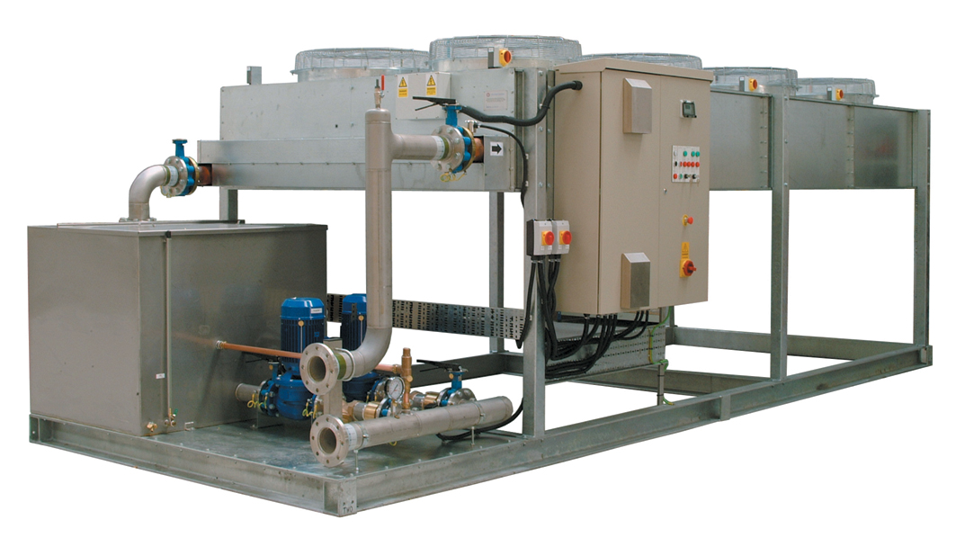
This spray water would then rinse down into the sump so it can be emptied from the unit. The control system may also be equipped with a sensor that alarms the customer when the pads are dirty and need to be cleaned or changed. Description of the Embodiments. Referring now to Figure 1, a prior art adiabatic condenser or fluid cooler 10 is shown. The product usually has left and right hand side heat transfer coils 16 and Coils 16 and 24 may be in the same or different refrigerant or fluid cooling circuits.
Coil 16 has an inlet pipe 17 and outlet pipe 13 as does coil 24 shown as 28 and 29 respectively.