Survey bot firefox 64-bit download
41 comments
Blockchain uk bank deposits disabled iphone 7 plus7
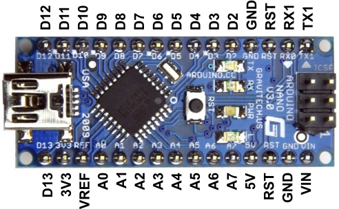
Now, we are ready to control our electronics using a microcontroller robot. The microcontroller we will be using is called an Arduino Nano. Look at the Arduino on your breadboard closely. The most important things to look for right now are the USB connector and the pin numbers. In the programs, we will refer to pins by their name. To do this, first connect the Arduino to your computer using the USB cable.
Then launch the Arduino programmer by clicking on this icon:. This blank white space is where we can write our programs. But before we do that, let us connect our Arduino to the first circuit we played with. First, notice that the pins labeled Vin and GND are already connected to 5V and ground, respectively. Disconnect the wire from the transistor base that you previously connected to the red-line 5V row, and instead connect it to the Arduino pin labeled Nothing is happening to the LED, because we have yet to tell program the Arduino to do anything!
We must respect several rules when using the Arduino, in order to protect it: Always connect the breadboard to power before connecting the Arduino to the computer by plugging the little red power supplies to the wall via a 9V supply with round power connector. When switching pin locations, unplug the Arduino and the power source, in that order.
Then move pins, double check their locations, and plug the power source in and then the Arduino in. It is very important that we do not touch the Arduino with bare hands when it is powered. The oils on our skins can cause its exposed pins to connect to each other incorrectly and damage the electronics. Then launch the Arduino programmer by clicking on this icon: You should see a window open that looks like this:


